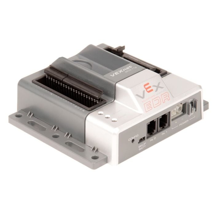
VEX ARM® Cortex®-based Microcontroller
The VEX ARM® Cortex®-based Microcontroller coordinates the flow of information and power on the robot. All other electronic system components must interface to the Microcontroller - it is the "brain" of a robot.
- STMicroelectronics ARM® Cortex® M3 user processor
- (8) Standard 3-wire Motor ports
- (2) 2-wire Motor ports
- (1) I2C "smart sensor" port
- (2) UART Serial Ports
- (8) Hi-res (12-bit) Analog Inputs
- (12) Fast digital I/O ports which can be used as interrupts
- Programmable with easyC v4 or ROBOTC for VEX Robotics v4.x
The VEX ARM® Cortex®-based Microcontroller coordinates the flow of all information and power on the robot. It has built in bi-directional communication for wireless driving, debugging and downloading using the VEXnet wireless link. The Microcontroller is the brain of every VEX robot.
VEXnet devices contain internal processors and run on special software called Firmware (or Master Code). Firmware is updated periodically to provide additional functionality or fix bugs. To fully unlock the potential of VEX Robotics VEXnet devices, it's important to ensure that all applicable drivers are installed and firmware is updated.
Please visit this page to download the correct firmware for your device.
(1) VEX ARM® Cortex®-based Microcontroller
VEX ARM® Cortex®-based Microcontroller / VEXnet Joystick User Guide
VEX ARM® Cortex®-based Microcontroller Pinout Guide
VEX Robot Troubleshooting Flow Charts
- 0.302 lbs (137 grams)
- The 8 analog inputs each consist of a 470K pull-up to +5V, a series resistance of 10K and a 20K pull-down resistance to the uP
Analog characteristics:
- 3 dB bandwidth of 16 kHz
- Analog input range: 0.0 v to 5.0 v
- Tolerant of -0.5v to +5.5v
- Only configurable as analog inputs
Digital Input Impedance:
- The 12 digital inputs each consist of a 1K series resistance and a weak processor pull-up to +3.3V. Each Digital Input can also be configured as a Digital Output
Interrupts:
- All digital inputs can be configured as interrupts except for Digital 10
- Usage: For 3-wire VEX motors, Motor Controller 29s or servos
- Type: Hobby standard PWM
- Refresh: Every 18.5 mSec
(2) 2-wire Motor Outputs
- Usage: For 2-wire VEX motors
- Type: H-Bridge
- Refresh: Every 1 mSec
(1) I2C "Smart Sensor" Port
- Usage: Future I2C Products
- 0 to 3.3v logic I/O
- Data rate, word width, etc set by compiler
- See Cortex Pin-out for wiring details
(2) UART Serial Ports
- Usage: VEX LCD Module
- 0 to 3.3v logic I/O, 5V tolerant
- Data rate, word width, etc set by compiler
- Factory default: 19.2 kbaud, 8 data bits, no parity, talks with VEX LCD
- See Cortex Pin-out for wiring details
- Analog In: 12-bit resolution. 10 μSec access time.
(12) Fast Digital I/O (can be used as interrupts)
- Digital In: 150 kHz input frequency
(1) DAC Speaker Output
- Usage: Output sound, voice, and music to an external speaker
(2) Rx1 & Rx2
- Connects to 75 MHz receivers
- Pin 1 - Power +5 volts (the right most pin when looking at the front connector on the VEX Controller)
- Pin 2 - Receiver
- Pin 3 - Gnd
- Pin 4 - Tether Detect (the left most pin when looking at the front connector on the VEX Controller)
- 3 dB bandwidth of 150 kHz
- Needs 0.0 to 0.6 volts for a low and 2.5 to 5.0 volts for a high
- Tolerant of -0.5v to +5.5v
- Can drive a 1 mA load to 1.6v or lower or a low and 1.4 volts or higher for a high
- All digital lines can be configured as inputs or outputs
SP characteristic:
- SP Output: A Digital-to-Analog (DAC) output when configured by compiler
- Drive primarily limited by 5K processor resistance
- Output swing into open load is 0.2v to 3.1v, typical
PWM Outputs:
- These 8 ports can drive an open circuit to 0.6v or lower for a low and 2.4 volts or higher for a high
- They can drive a 1 mA load to 1.0v or lower for a low and 2.4 volts or higher for a high
Pinout:
- Digital, Analog, PWM Outputs: Outside pin (closest to the controller edge) Ground
- Digital, Analog Outputs: Center pin (or middle pin) + 5 Volts, 1 Amp Max combined total from all pins
- PWM Outputs: Center pin (or middle pin) + Battery Power, 4 Amps Max combined total from all pins for Motors 2 - 5 and 4 amps combined for Motors 6 - 9
- Digital, Analog, PWM Outputs: Inside pin (furt.hest from the controller edge) Signal / Control line
2-Wire Motor Outputs:
- Two pins each for Motor 1 and for Motor 10
- Motor 1 shares 4 amp max with Motors 2 - 5
- Motor 10 shares 4 amp max with Motors 6 - 9
- Speed - 90 MIPS (Million Instructions Per Second)
- RAM - 64KB
- Flash - 384KB program space
Click the button next to a file to view it in your browser.
